Harber Metal MIM Design Guide
Metal injection molding (MIM) or powder injection molding (PIM) is a net forming process used to manufacture extremely complex metal components in medium to large batches. When applying MIM/PM to new components and evaluating whether existing components can be converted to MIM/PIM manufacturing technology, reference can be made to this design guide. By ensuring the net forming results and expected dimensional Cpk values, designing reasonable MIM parts can achieve maximum process efficiency.
Harber MIM consists of an excellent team composed of design engineers, metallurgical engineers, process engineers, production and manufacturing personnel, and quality engineers - each member has rich experience in metal injection molding (MIM) or powder injection molding (PIM). Our experienced technical team is renowned for its advanced processing and analysis equipment, helping you develop MIM applications or modify components manufactured using other processes.
Harber can provide quotations or design assistance, and you can send us an electronic document of your part information via email. Our application software includes Pro Engineer Wildfire, UG, Inventor, and AutoCad/Mechanical Desktop. Please provide CAD files in the following formats:. pdf,. dxf,. igs,. stp (. step), or surface igs.
Metal injection molding (MIM) or powder injection molding (PIM) is a net forming process for manufacturing solid metal parts, which combines the design flexibility of injection molding with material properties similar to forged metal. Due to its inherent design flexibility, MIM can manufacture products of any shape using multiple alloys. Today, many products use MIM in high-performance applications, including automotive fuel and ignition systems, aerospace and defense systems, mobile phones, dental instruments and dental reinforcement tools, electronic radiators and sealed packaging, junction boxes, industrial tools, fiber optic connectors, fluid spraying systems, hard drives, pharmaceutical equipment, handheld electric tools, pumps, surgical instruments, and sports equipment.
When developing the geometric shape of metal parts using MIM technology, attention should be paid to the flexibility of plastic part design, breaking free from the limitations of traditional metal processing techniques. MIM technology can handle complex part shapes, combine multiple components, integrate multiple features/functions within a single component, enhance product assembly performance, simplify mechanical components and reduce weight, and can customize various physical properties according to the expected ending use.
MIM is the most cost-effective process for manufacturing small and complex metal components in medium or ultra large batches. The method of evaluating an alternative application is to imagine how many processing operations are required to manufacture a product of a certain shape. Generally speaking, for component designs that require 4 or more processing steps or operations, MIM is the preferred process. Note: For each machined feature, machining will increase costs;
For molded shapes, MIM adds minimal or even no cost at all. Figure 1 shows the cost-part complexity comparison between MIM and other manufacturing processes.
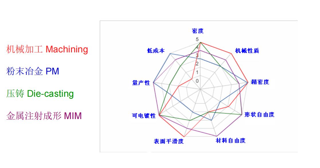
The following are the general characteristics that describe the good application of MIM:
Part of the parts
Length less than 160mm
Wall thickness less than 10mm
Weight above 100 grams
The annual production is only 5000 pieces
Most parts
Length less than 70 mm
Wall thickness 1 to 5 mm
Weight less than 60 grams
Annual production of 100000 to 100000000 pieces
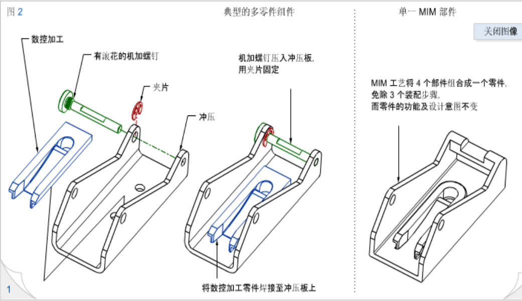
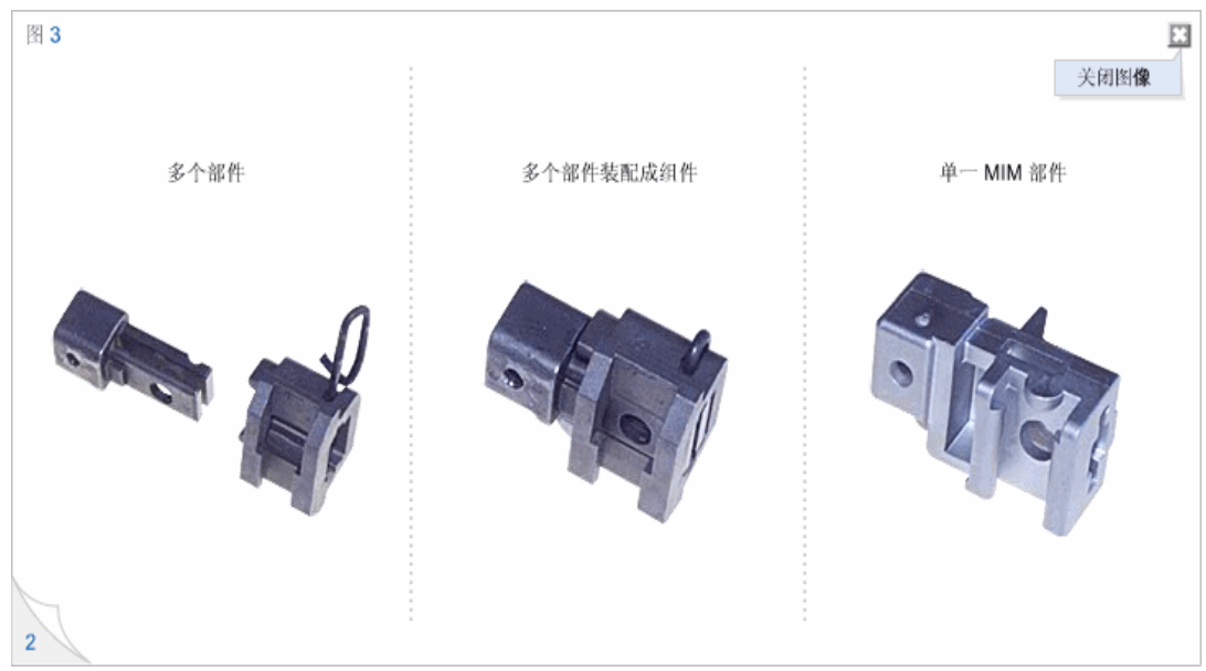
MIM itself is designed to be flexible and can combine various components within a component into one MIM component, greatly improving efficiency. Figure 2 shows converting a component containing four components into a MIM component. This can save three assembly steps and related costs, and also reduce the number of parts that need to be purchased, tracked, and stored. The MIM components produced are more robust, cost-effective, and more in line with the original design intent than the components. Figure 3 shows the practical application of this design method. Combining three components into one improves product performance at a much lower cost.
To achieve the best cost-effectiveness from MIM, it is usually necessary to consider technical factors when designing applications, but successful technology conversions occur in daily work. From preliminary cost analysis to comprehensive dimensional review of tolerance specifications, Harber MIM design engineering team will assist you in evaluating possible technical conversions.
MIM Design Standards
Uniform wall thickness, core pulling and reduced mass
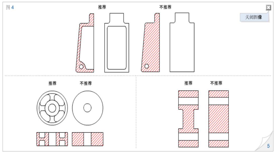
Due to injection molding being a forming process in MIM, part design can overcome the limitations of traditional metal processing techniques. For example, mechanical processing involves planing materials from solid objects to produce the final required components. So, when making design decisions, design engineers can only consider the problem from the perspective of manufacturing economy and cannot exceed the design limitations of mechanical processing. Usually, removing excess materials from components is not considered to reduce quality, as this design method further increases machining costs. If it is similar to injection molding MIM, design engineers can freely start designing on the "whiteboard", cut materials according to functional and strength requirements, and construct the geometric shape of the components. This can bring several benefits to the MIM process and customers. The metal powder used in MIM technology is extremely fine and expensive, and any savings in the amount of materials required for components can help reduce the final cost of MIM components. In addition, the uniform thickness of each part of the component can reduce the possibility of defects during the forming process, improve the overall quality of the component, and usually improve the final dimensional tolerance of the MIM process.
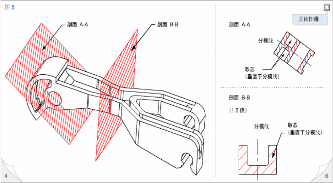
Figure 4 shows several preferred shapes achieved by generating uniform wall thickness through core pulling. You can also see several examples of removing excess materials or extracting cores from thick sections. Cores can be drawn parallel or perpendicular to the parting line. Figure 5 shows two core pulling methods. Multiple cores can be drawn perpendicular to the parting line (A-A section), which are fixed features on any half of the mold. Core pulling parallel to the parting line (B-B section) can have row positions, which are the moving parts of the mold. Rows are usually placed on the parting line and move along the parting line. The row position increases the complexity and cost of the mold, so if the design allows, a core pulling method perpendicular to the parting line is preferred.
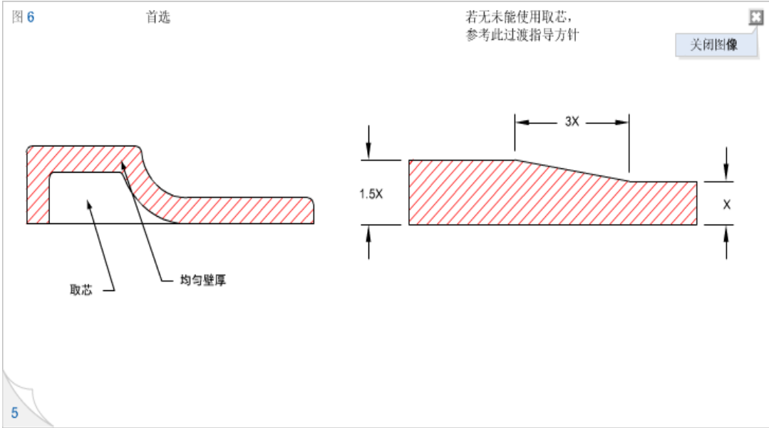
Attention: When designing MIM parts or extracting cores from existing parts, maintaining uniform wall thickness is the main goal. Furthermore, for MIM components, uniform wall thickness will make the parts more precise, have better dimensional repeatability, lower processing costs, and be more aesthetically pleasing. However, if uniform wall thickness cannot be guaranteed, a gradual change in wall thickness should be achieved to avoid steep changes as much as possible. Figure 6 provides the recommended wall thickness gradient for situations where uniform wall thickness cannot be achieved.
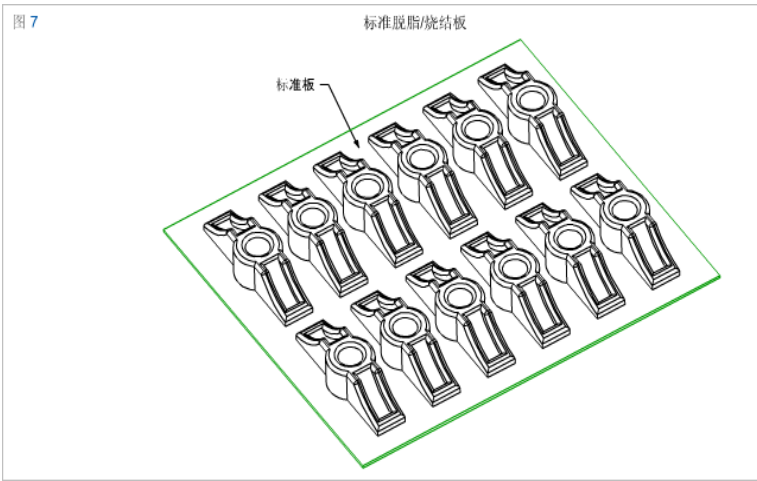
Standard degreased sintered board
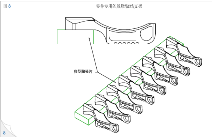
specific degreasing and sintering support
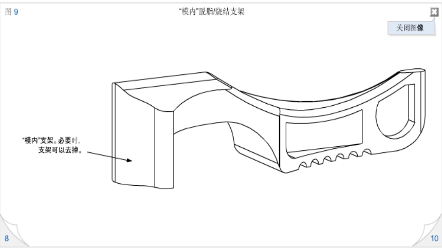
Mold support, the support could be removed if necessary.
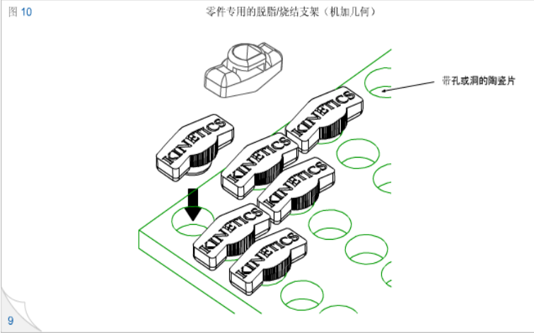
Special degreasing and sintering bracket for parts (machined)
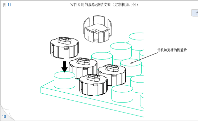
Ceramic sheets with machine added support rods
Sharp corner rounding and rounded corners
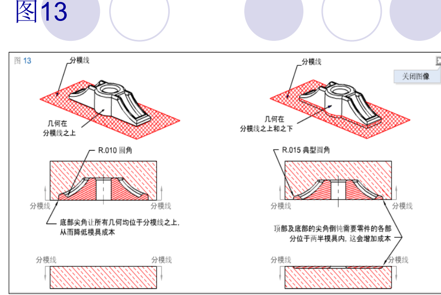
One of the inherent benefits of MIM is its ability to blunt sharp corners and generate rounded corners. Sharp chamfering and rounded corners are not only important aspects of good MIM component design, but also bring design engineers design advantages that certain metal processing techniques do not possess. In addition to improving the quality of injection molded parts, these design advantages also include improving part strength, eliminating stress concentration, and beautifying the appearance by passivating sharp corners
The injection molding process used by MIM is easy to punch and groove, and generally speaking, this process does not increase the cost and unit price of the parts. However, adding these features does increase the cost and complexity of the mold. It should also be noted that in addition to having functional significance, holes and grooves can also be used to reduce part quality, provide uniform wall thickness, etc.
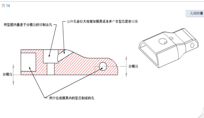
It is important to know the type and direction of the hole, as well as how it affects the cost and strength of the mold. Figure 14 shows several types of holes, their orientation relative to the parting line and their impact on the mold. For holes with vertical parting lines, mold design is the easiest and mold cost is the lowest. Holes parallel to the parting line are easy to apply, but the processing cost is higher than holes perpendicular to the parting line because such holes require mechanical positioning or hydraulic cylinders to perform functions during the ejection process of the part. Holes can also be at a certain angle to the parting line, but mold construction and punching mechanisms can become very expensive. In many cases, mold features require more frequent downtime and high maintenance costs.
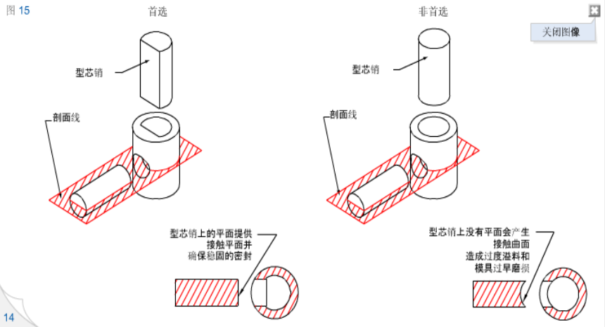
If the core and groove intersect, it can also make the parts more complex. However, in order to apply intersecting features, it is necessary to consider the construction and robustness of the mold. Figure 15 shows the advantages of using a D-shaped hole as an ideal sealing surface for a cross hole. In this example, two flat surfaces are sealed against each other, making the mold easy to maintain, and it is unlikely to experience unacceptable overflow during the molding process. This figure also shows another ineffective method, which requires one of the cores to have a curved surface and pair with the blocked core or hole during the injection stage of part molding. In such cases, the orientation of the core becomes crucial, and the edges quickly wear out, affecting the shape and size of the forming features. In addition, mold overflow is also a problem to be aware of.
External/Internal groove
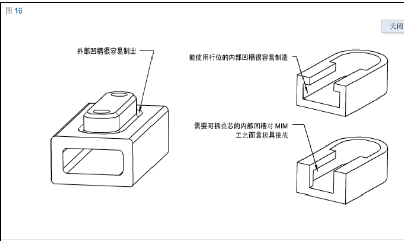
The MIM process makes it easy to create external grooves. The component on the left side of Figure 16 shows that an external groove has been used to solve the burr problem of paired stamped components. MIM can incorporate corresponding features into mold design, eliminating the need to remove burrs from stamped parts and eliminating related expenses. In essence, MIM can manufacture more complex parts without increasing costs. At the same time, there is no need for secondary removal of burrs or chamfers like stamping parts. When designing components manufactured using MIM technology, the requirements for product assembly should always be considered.
Under appropriate conditions, MIM can also produce internal grooves. The internal grooves that can use mechanical or hydraulic positioning are easy to manufacture. Figure 16 (upper right) shows an internal groove of a T-shaped groove made of row positions. Figure 16 (bottom right) shows a similar component, but the internal groove requires a detachable core. This groove requires sufficient internal features to accommodate a sturdy and detachable core. However, overall, MIM components are small, detachable cores are usually not practical, and sometimes they are not strong enough to withstand the injection pressure used in MIM forming processes. The detachable core also increases the difficulty of maintaining and reducing burrs. When considering these characteristics, suggestions can be sought from Harber Metal Application Engineering Department
The internal thread can be directly formed inside the component by loosening the core. These mold features and functions have high production costs, so they are only suitable for mass production of parts. For small-scale production of parts, traditional tapping methods can be used
Traditional method
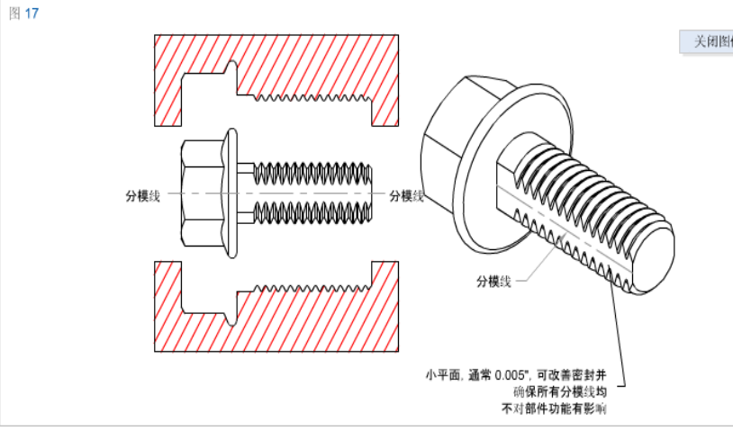
xternal threads can be directly formed on components without the need for secondary threading operations. Compared with the method of processing threads with secondary operations, the method of directly forming external threads with molds is more cost-effective. Generally speaking, in design, a small plane with a size of 0.127mm should be considered at the parting line. The embedding plane shown in Figure 17 will ensure appropriate mold sealing and reduce the chance of interference from parting line marks on component functionality. If there is no plane along the mold line, you can expect that in very few parts production, there will be overflow problems at the root of the thread. This is likely to increase mold maintenance and downtime.
Reinforcement and plate
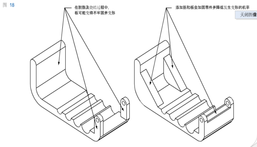
Ribbed structure is an effective way to improve the strength of parts, which can minimize the size changes caused by significant shrinkage during degreasing and sintering. In plastic injection molding, the rib plate structure can also improve the molding process and better control the size. Figure 18 provides a detailed explanation of how to add rib plates to improve mechanical design and produce more robust MIM components.
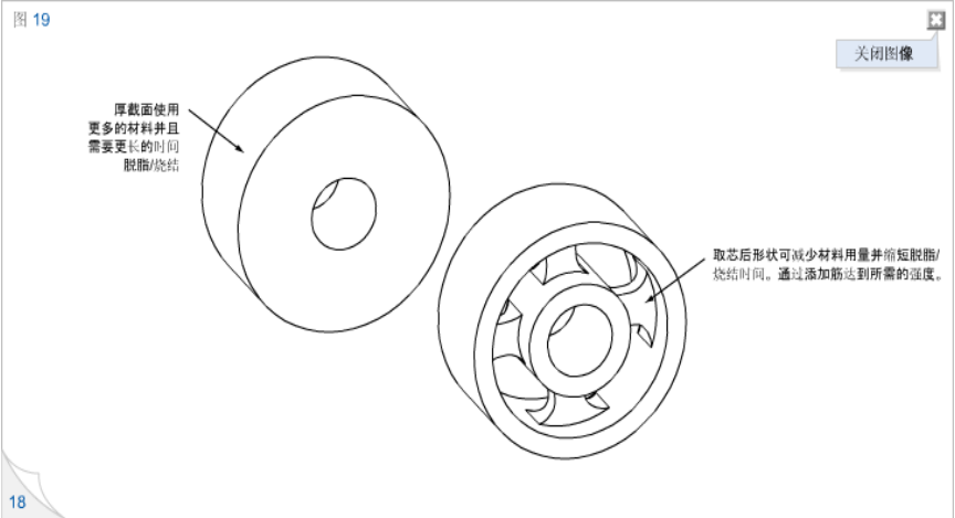
Figure 19 shows another application of rib structure, which reduces the weight of parts by core pulling without affecting the final design purpose or strength of the components
Knurling, engraving, and logo
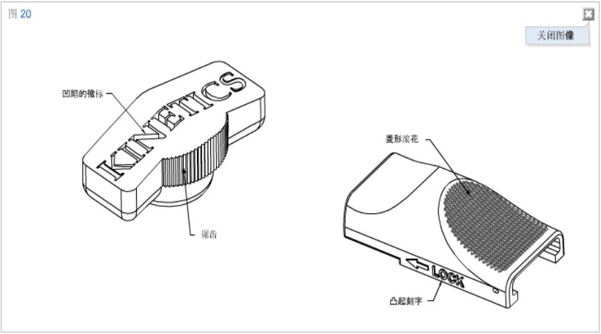
MIM can directly emboss, print, create logos, engrave date codes, or other design patterns on components without increasing unit cost. These features can be either convex or concave. Figure 20 shows different examples of this feature. MIM can perform high-level fine processing on features. Including relatively clear diamond knurling. MIM technology can shape almost any pattern feature on solid metal parts
Gate - Type and Location
Similar to injection molding, MIM parts also require consideration of the position of the gate. However, due to the large amount of metal powder added to MIM raw materials, its gate is generally much larger than that of plastic parts.
In most cases, the gate is located at the position of the mold parting line. During the design phase, it is necessary to consider the impact of gate position on the components, as the determination of gate position requires a comprehensive balance of factors such as manufacturability, part functionality, size control, and aesthetics. The gate will leave subtle marks, so it should not be located on surfaces that have important requirements for size or appearance.
Generally speaking, the gate is located on the thickest section to allow the raw material to flow from the wall section to the thinner section. In addition, the position of the gate should also be such that it can evenly fill the mold cavity.
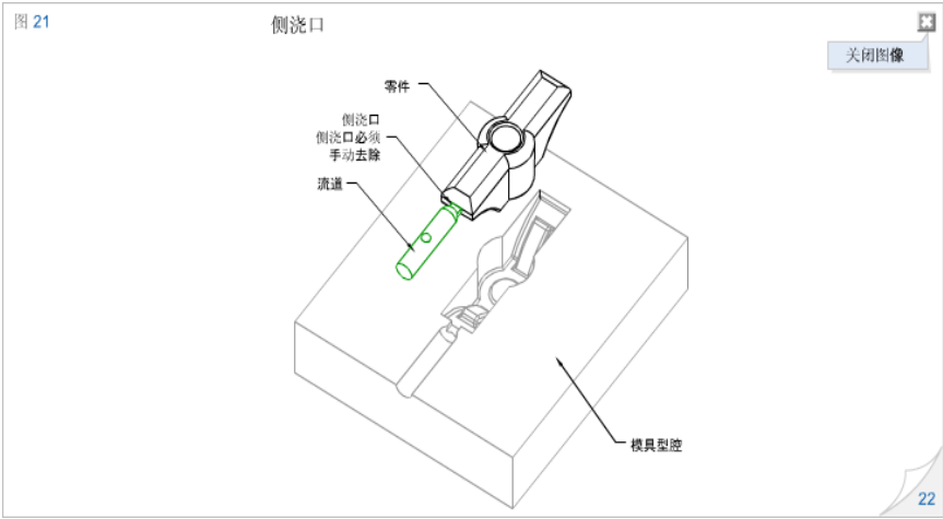
Figures 21-23 show examples of different types of gates and their typical applications and preferred locations.
Figure 21 shows an illustration of a side gate. The following are typical features of side gates:
Gates are usually manually removed. Due to the need for manual or automated removal of the gate, it is not suitable for situations with high annual production. Removing the gate will always require additional processing and increase costs.
It is only suitable for occasions where small and medium-sized batches are produced every year.
The concave gate is the preferred type of gate, which leaves the least trace on the surface of functional components.
Generally distributed along the parting line.
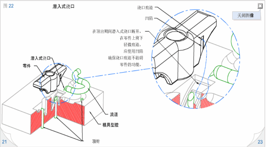
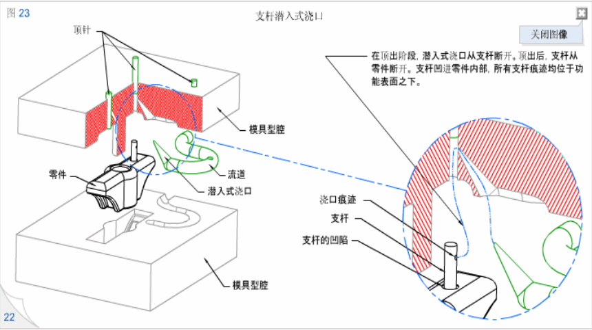
Figure 22 details the submerged gate, which has the following characteristics:
During the ejection stage of the forming process, the gate automatically disconnects from the part.
Suitable for occasions of annual production from small to large quantities.
The trace left by the gate is the lightest, or it may break off from the component below the outer surface.
A submerged gate should be used on the concave surface to minimize the marks on the surface of the functional components.
Concave and Joining Lines
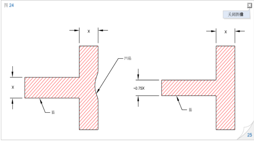
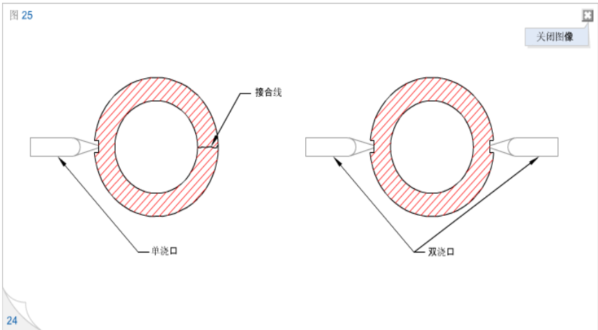
Similar to injection molded parts, MIM parts may also experience dents and joint lines due to improper part and mold design. Dents (physical pits on the surface of parts) usually appear in thicker parts. Figure 24 shows how a depression occurs when a supporting rib intersects with a wall. If the thickness of the reinforcement is the same as the wall thickness, the intersection of the two will form a locally thick wall, which is prone to causing depressions. Reducing the thickness of the support bars can eliminate or reduce the possibility of depressions occurring. Generally speaking, the thickness of the reinforcement should be around 75% of the wall thickness. When the two flow channels of the raw material meet in the mold cavity and the flow channels are relatively long, a joint line will be formed. Figure 25 shows the joint line that appears on a single core and single gate cylindrical part. Before the two flow channels meet on the opposite side, they must extend around the core. Due to the long flow channel, a visible joint line will be formed when the front end of the raw material flow cools down. Figure 25 also shows that setting double gates on the parts can greatly reduce or even eliminate visible joint lines. Please remember that the joint lines on well-designed MIM parts are almost invisible, indicating no structural defects or performance issues with the parts. Usually, this type of joint line has a shallow flow mark with a depth of 0.01 to 0.1 mm
Minimum wall thickness and maximum wall thickness
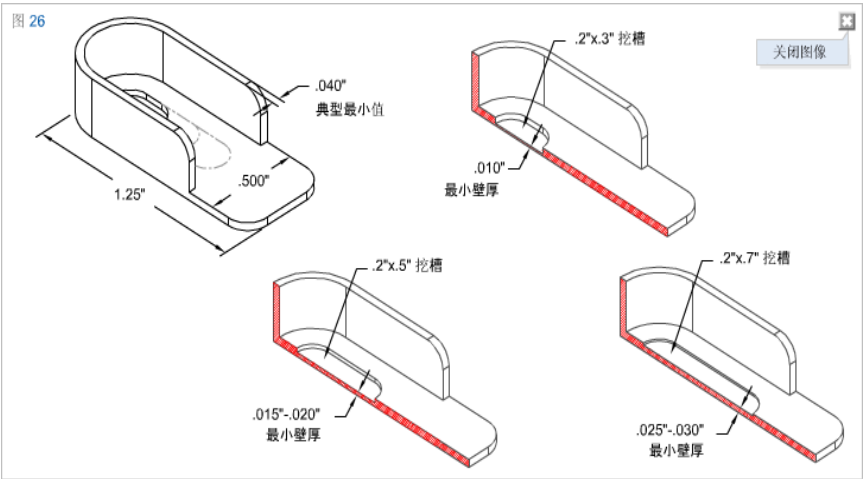
The minimum or maximum cross-sectional thickness on any part mainly depends on the overall size and design of the part. Whether the MIM process can fully pour the parts during the forming process is the most important issue that needs to be paid attention to. For example, if the local thickness is 0.20mm, it can be fully filled, but if the thickness spans the entire length of the 100mm part, it cannot be fully filled. Generally speaking, the optimal wall thickness is between 1mm and 3mm, but of course, the specific ideal thickness depends on the overall size of the part. Reducing wall thickness can reduce the amount and cost of raw materials used in parts. Figure 26 shows a thin-walled MIM part with a small groove. The figure shows the general guiding principle that the minimum possible wall thickness depends on the size of the excavation. The maximum wall thickness can be as large as 10mm, but as the wall thickness increases, the consumption of raw materials correspondingly increases, and the forming cycle, as well as the degreasing and sintering cycles, will be extended. The increase in each of the above steps represents an increase in component costs
Overflow and trimming
When designing a MIM component, consideration should be given to the areas of burrs and potential overflow. For important areas that focus on aesthetics and functionality, the potential impact of trimming or how to minimize the possibility of overflow should be evaluated. It should be noted that MIM feed is more prone to overflow than most plastic raw materials, so MIM molds require precise matching between each mold component (such as row position, core, etc.) and the parting line. Remember, the overflow generated on MIM parts will turn into metal burrs after sintering, making it difficult to remove.
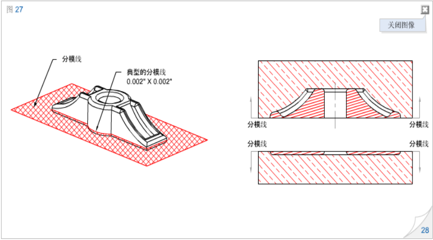
Flash is an unavoidable product of two paired mold components. Whether it is along the parting line, sealing a row with a core pin, or other mold features, the injection molding material under pressure will leave a flash mark when two steel parts meet. Figure 27 shows a typical flash expected to occur along the parting line. In this example, the parting line is located exactly above the fillet, and the flash will wrap around the entire part at this point. Flash edges can sometimes be reduced or completely removed by secondary lighting. As mentioned in the "Sharp Corner Blurring and Rounding" section of this design guide, if bottom rounding is not required, sharp corners can be used, and the entire part can almost be placed on the top half of the mold. This way, the parting line can be moved to the bottom of the part, and there will be no burrs. The polishing operation will cause slight sharp corners to blunt, so there is no need to place the entire part in the two halves of the mold to arrange the radius along the edge of the part.
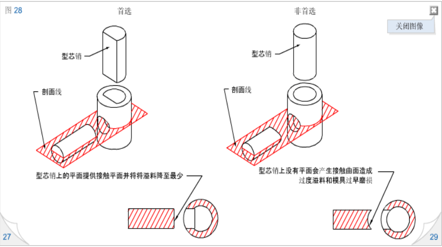
The possibility of overflow always exists, and in many cases, the construction of the mold plays an important role in minimizing this possibility. However, some measures can also be taken in the design to improve the strength of the mold, which can also reduce the chance of material overflow on the parts. One main method to avoid overflow is to create a "flat flat" contact between the mold sealing components. Figure 28 shows the use of D-shaped holes as the ideal sealing surface for cross holes, and the redesign of two cross holes to reduce the possibility of overflow.
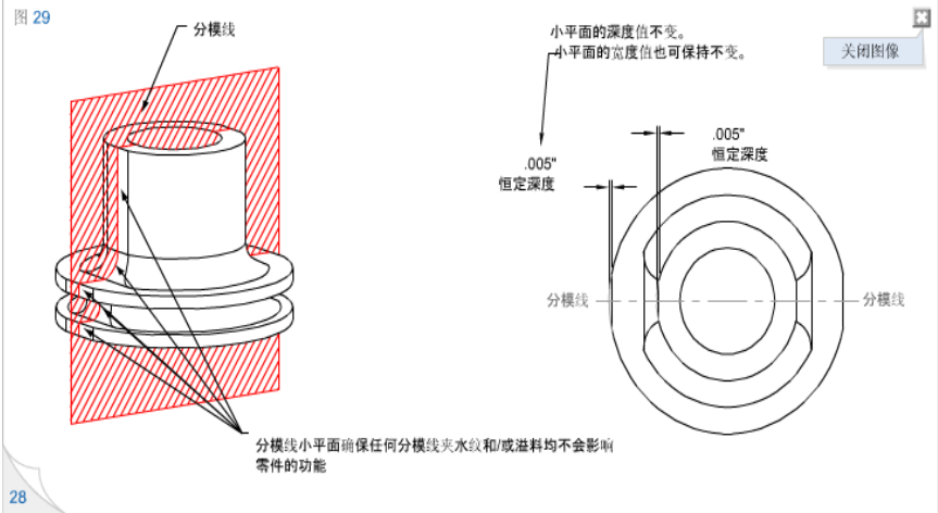
In this example, two flat surfaces are sealed against each other, making the mold easy to maintain and it is unlikely to experience unacceptable overflow during the forming process. This figure also shows a poorly performing method that requires one of the cores to have a curved surface and pair with the blocked core or hole during the injection stage of part forming. In such cases, the orientation of the core becomes crucial, and the edges quickly wear out, affecting the shape and size of the forming features. In addition, mold overflow is also a problem to be aware of. Try not to place areas that may have overflow and/or flash edges in important areas of the parts. If this cannot be achieved, other methods can be used to ensure that flash and/or overflow do not affect the functionality of the parts. Figure 29 shows one of the alternative methods. For cylindrical components with external grooves, the parting line can extend vertically downwards to the center of the part. To avoid burrs on the outer diameter affecting the functionality of the component, add small planes along the parting line to ensure that burrs and/or overflow occur below the functional diameter of the part.
Dimensional tolerances
Firstly, it should be pointed out that the tolerance after MIM sintering can reach:
0.3% of rated value (i.e. 25mm 0.075mm)
The tolerance of investment casting process is:
0.5% of rated value (i.e. 25mm 0.125mm)
The precise tolerance size of any feature is influenced by various inherent variation factors in MIM technology. The final tolerance size may be less than ± 0.3% mentioned above, or in some cases larger than this value. Factors such as part design, size, shape, raw materials, gate position, number of cavities, mold construction technology, annual output, and inspection technology need to be taken into consideration. The chemical properties of specific raw materials have a significant impact on tolerances. Not all raw materials have the same impact on tolerances. Measurement or inspection requirements are a part of component design and have a significant impact on the size of tolerances. Our experience is that theoretical intersections, radius centers, and very small features may require larger tolerances due to factors such as measurement resolution, repeatability, and performance limitations. Harber MIM design engineers will discuss measurement design issues with you when helping you complete the components.
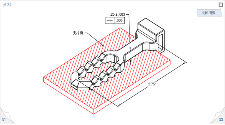
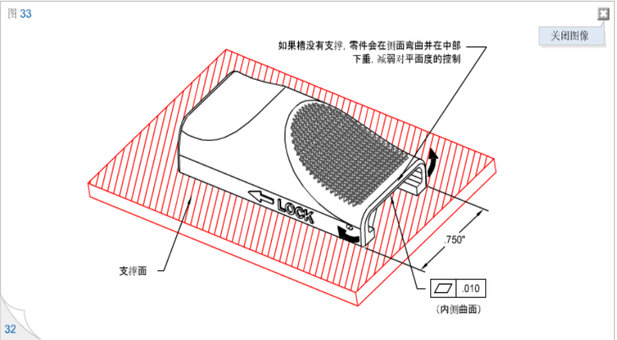
According to the different geometric shapes of the components, the lower limits of flatness and straightness can reach 0.1%, which is every 10mm,the tolerance is 0.01mm. If the entire main surface is supported during the degreasing and sintering processes, or if the main features are perpendicular to the supporting surface, the above goals can be fully achieved. The position of the gate, cross-sectional thickness, and cross-sectional geometry will affect the final straightness and flatness. Figures 32 and 33 show examples of different MIM shapes and final flatness or straightness
Secondary processing
To minimize the cost of secondary processing, the commonly used tolerance guidelines in this design guide should be used. If someone
If the tolerance required for a feature is smaller than the tolerance that can be achieved by MIM technology, then secondary processing is required. MIM metal materials can be machined, threaded, drilled, opened, processed to a certain size, polished, or welded like forged parts. To adapt to the annual large-scale production, Harber MIM has developed a fully automatic secondary processing method to minimize the cost of these additional processing.
heat treatment
Similar to forged components, MIM components can also undergo heat treatment to improve material strength, hardness, and wear resistance. MIM 4605 material can undergo standard heat treatments such as quenching and tempering, isothermal quenching, induction quenching, or surface hardening processing.
Surface polishing and electroplating
The density of components manufactured by Harber MIM metal injection molding process is generally equal to or greater than 97% of the theoretical density of forged materials. High density typically results in a surface finish of up to 32 after sintering μ In Ra. After secondary processing, such as polishing, grinding, and polishing, the surface smoothness can be higher than 16 μ In Ra. To learn more about surface finish, please refer to the "Material Properties" section on our website homepage. Shanghai 3S MIM materials can be electroplated or use the standard process of forging materials, without the need for special surface treatment. Here are some examples of electroplating and surface treatment: non electrolytic nickel, chromium, zinc, chromates, nickel iron fluoromers, black oxidation, and passivation.


